| 2 Controls and Connectors |
|
|
Description of Controls and Indicators on Front Panel
|
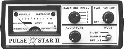
| Fig. 4: Front Panel |
PWR VOLUME
With this control knob you can switch the PULSE STAR II ON and OFF. Simultaneously you can adjust the volume of the ticking-rate of the built-in speaker as well as for the connectable headphones.
When the PULSE STAR II has been switched on, both LED lights (green and red) come on for approximately five seconds. During this time the PULSE STAR II will automatically adjust itself. The needle of the meter is set to zero and the preset ticking-rate is recalled.
The MODE toggle switch must be positioned to NORMAL in order to hear any ticking noise. You will not hear any ticking noise in the SILENT mode position.
AUDIO TUNE
With the AUDIO TUNE knob the initial ticking-rate can be controlled by holding down the MODE switch to RETUNE and simultaneously turning the AUDIO TUNE knob.
The ticking-rate should be calibrated between one and five clicks per second.
MODE
The MODE toggle switch can only be locked in the NORMAL or SILENT position. The RETUNE mode is momentarily.
1. NORMAL
The PULSE STAR II has the highest sensitivity for detecting targets in this position. There is no motion of the search coil necessary to get a reading. Adjustment of the ticking-rate is possible in this position.
2. RETUNE
You can recall the preset ticking-rate by switching to this mode.
3. SILENT
There is no ticking noise or continuous audio sound in this mode. In order to get an indication, movement of the search coil is required. If any ferrous object*) is detected you will hear a low pitched tone with a green light response. If any non-ferrous objects are found you will hear a high pitched tone with a red light response. You will loose some sensitivity (approximately 20 to 40 % in depth) while operating in the SILENT mode.
*) See chapter 1 (Function) for further information about the metal discrimination.
SAMPLING DELAY
Operating the PULSE STAR II in the NORMAL mode with SAMPLING DELAY control knob in position 1 will give you the greatest sensitivity of any object detected.
In positions 3 and 4 the sensitivity to ferrous objects and thin foils are greatly reduced. Smaller iron objects as well as foils can be completely eliminated. In chapter 3 (Detection Depths) an illustration is given showing how the position of SAMPLING DELAY influences the detection depth of different objects. Additionally, you can minimize the effects due to highly mineralized soils when using a higher SAMPLING DELAY position (see chapter 6).
The PULSE STAR II also retunes itself when changing from one control position to another (both LEDs turn on). It is not necessary to press the MODE switch to RETUNE after you changed a SAMPLING DELAY position.
INTENSITY METER - DISC INDICATORS
The INTENSITY METER indication will increase as you pass over any buried object.
If you hold the MODE toggle switch down to RETUNE for more than one second, the battery condition can be checked. If the meter needle is shown near or in the black area, the battery needs recharging.
| During operation a warning sound of several beeps occuring every seven seconds will alert you that the battery needs recharging. See chapter 7 for more information. |
On the meter plate you will see two LED indicators, a green light for ferrous and a red light for non-ferrous. Also, both LEDs will light when the PULSE STAR II is turned on, when you use RETUNE and when you change a SAMPLING DELAY position. In each case this indicates an automatic retuning of the PULSE STAR II.
A detailed description will be given in the following chapters of how to use the PULSE STAR II in actual practice.
Description of Connectors and Indicators on Rear Panel
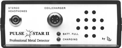 |
| Fig. 5: Rear Panel |
COIL/CHARGER
Different size coils can be connected to this jack. Push the connector plug in all the way before turning the sleeve on the plug. Locking the plug will keep the connector from pulling out.
Furthermore, the built-in battery can be recharged via this jack.
STEREO HEADPHONES
You can connect any type stereo headphones with a 1/4 inch (6.3mm) phono plug to this outlet. One set of stereo headphones is provided (which includes an adaptor). The built-in loudspeaker is automatically turned off when headphones are plugged in.
CHARGING
The green LED light indicates that the battery is charging.
BATT. FULL
The red LED light indicates the battery has been fully charged. The charging will automatically be stopped and the charging electronic changes to holding state. However, it is recommened to disconnect the charger when the red LED turns on.
See chapter 7 (Maintenance and Charging) for detailed charging instructions.
| Chapter 1 | Chapter 3 |