Brief description of the IR Controller
Overview
Requirements Features
& Operation Connections to
the PC hardware
Back to the first page
The main reason for developing the IR Controller was to add the possibility of turning on the VDR by the IR remote control. It has has some additional features and can be further enhanced by software changes and hardware extensions (for example outputs for status LEDs).
The IR controller consists of an IR receiver chip, a PIC16F628 micro, and a few standard components. I chose the Philips RC5 code as this is widely used, very reliable (bi-phase coding), and has a toggle bit. Please note that the IR Controller does not replace LIRC, but works as an add-on.
It has been designed using SMDs and a double sided PCB. Sorry if all this is too technical, but this page is not for advertising a commercial product, but only for those who are able to handle a soldering iron :-)
Update 24 Jan 2003: Now a single
sided PCB with standard components is also available.
Go here for details.
Requirements [Top of page]
Features & Operation [Top of page]
IR remote power key to turn VDR on/off
If the ATX power supply is in standby, VDR can be turned on by pressing the
remotes' power key for at least one second. If VDR is running, pressing the
remotes' power key invokes the shutdown script as usual.
PC power switch to turn VDR on/off
The PC power and reset switches on the PC front panel could be pressed unintentionally,
causing an unwanted hard reset. The IR Controller solves this problem as follows
(provided that the hardware changes described below have been applied): If VDR
is in standby, pressing the power switch will simply turn on VDR. If VDR is
running, pressing this switch will cause the IR Controller to send a software
generated RC5 code directly to LIRC via the RS232 interface. This way, the usual
VDR shutdown script can by initiated. If necessary, pressing and holding the
power switch for at least 5 seconds will cause the IR Controller to reset the
PC immediately via the reset input of the motherboard. Therefore, the reset
switch becomes redundant.
RS232 level within specifications
All of the home brew LIRC receivers use only a single 5 volts supply. However,
the RS232 specs require signals of ± 5 to ± 15 volts. The range
from -3 to +3 volts is undefined. Additionally, the IR receiver chips may not
pull their output fully down to GND (depending on the external pullup resisor).
This makes it even worse, but still most of the RS232 interfaces will tolerate
this. The IR Controller level shifts the incoming signals as well as the PIC
generated codes to ± 5 volts which is within the specs.
Learning mode
You can enter a learning mode to teach the IR Controller which key of the remote
transmitter should be used for turning on/off VDR. All other keys are still
defined in LIRC. Also, a boot delay time (*) for the status LED can be entered.
The learning mode can be activated when VDR is in standby (LED is red) by pressing
and holding the '0' key for at least 5 seconds. (Note: the '0' key of any RC5
remote control will be recognized even though the IR Controller hasn't learned
it). The LED will flash 4 times alternately red/green and will then turn off:
the learning mode has been reached. Now press three keys one after the other:
10's of the boot delay (in seconds), 1's of the boot delay, required power-key.
Do not wait for more than 5 seconds in between each key press, otherwise the
leaning mode will be aborted. After pressing the three keys, the learning mode
will be left. Example: <4> <5> <your power-key> will set the
boot delay to 45 seconds and <your power-key> is now used to turn on and
off VDR. It will be verified that the first two keys are 0...9 and the third
key is not 0...9. These are invalied entries and they will be ignored
(the timeout of 5 seconds will be restarted in this case). Any valid entry will
be indicated by a short green LED flash.
Note: By the initial programming of the PIC the following default values will be stored in the PIC's EEPROM: 45 seconds boot delay, URC-7040 PWR-key (code # 0081).
(*) Boot delay: As the IR Controller does not know when VDR has completely booted, you can enter a delay (i.e. the time between turning on VDR and the appearance of the TV picture) of up to 99 seconds. This time only determines when the LED stops flashing green and turns continuous green.
Emergency reboot
If you press the 0-key for at least 5 seconds while VDR is running, the IR Controller
will send a special RC5 code to LIRC. Suitable entries in lircd.conf and lircrc
can now call a reboot script via irexec.
Bicolor status LED
A bicolor LED (red/green) turns on or flashes as follows:
| VDR standby | red |
| VDR booting | flashing green (while no remote commands are accepted) |
| VDR running | green |
| VDR shutdown | flashing red (while no remote commands are accepted) |
Additionally, there are some special LED signals related to the learning mode. Also, each time a valid RC5 code has been received, the LED turns off for 50ms. As the RC5 code repetition rate is 114ms, it will actually flash 9 times per second. The RC5 decoding is very reliable, so no codes from other keys or other IR transmitters can start VDR.
ICSP-Interface
The PIC micro can be programmed via this interface (Microchip's ICSP = In Circuit
Serial Programming). Hardware extensions can also be connected here.
Connection to the PC hardware [Top of page]
The power and reset switches must be unplugged from the motherboard.
The connector at the end of the power switch cable must be plugged to the pinheader
labeled PWR-SW on the IR Controller. The (now unconnected) power and reset pin
headers on the motherboard must be connected by two wires (ground is not needed)
to the pinheader labeled RESET/PWR of the IR Controller. As Christian Vogt suggested,
it might be a good idea to use two reed relays instead of the two transistors
on the IR Controller for power and reset. This way, you would't have to find
out which of the pins is ground. Update: The thru-hole
version does use reed relays, so you don't have to bother about the ground
pins. Use two separate cables (two wires each) to connect the respective outputs
of the IR Controller (now labeled FPBUT_IN and FP_RST#) with the motherboard's
power and reset pinheaders.
A 10-wire ribbon cable with 10-pin connectors on either side is used to connect
the motherboard's RS232 (usually a 10-pin header for COM2 is available on the
MB) with the IR Controller's pin header labeled RS232. If you already use a
serial LIRC receiver, remove it and connect the controller here. Only two wires
are actually used, data and ground. Update: A
third connection (DTR) is added now for both SMD and
thru-hole versions. This can be used for receiving commands via LIRC's
rc in conjunction with a new PIC firmware.
The IR receiver chip and the bicolor LED can be soldered
directly to the PCB or separated by connection wires.
The +5 volts standby (brown) and -5 volts (white) of the cable bundle coming
from the ATX power supply must be tapped using tap splices and connected to
the IR Controller. It is very important to ensure well
isolated connections. Also, small fuses (ca. 500mA) should be inserted directly
after the taps. You can use shrink tubing for the fuses (being optimistic
that they will never blow) or inline fuseholders.
Notes:
(1) If your motherboard has a WOL (Wake On LAN) pinheader, the +5 volts standby
voltage is also available here.
(2) If your ATX power supply doesn't have -5 volts, but only -12 volts, you
can use this as well.
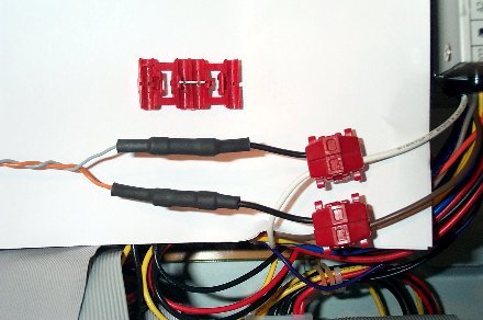
Here is a picture showing the taps. You can see the two tap splices (plus an unused open one, see parts list) and the the two fuses covered by shrink tubing. This provides a very good electrical isolation.
Top of page Back to the first page